Stirling stirlingmotor engines Schematic of alternative design (stirling cycle), with a regenerator Stirling pv figure
Low Temperature Difference – Stirling Engines
Cycle stirling ume idealised
The schematic representation of the stirling's cycle
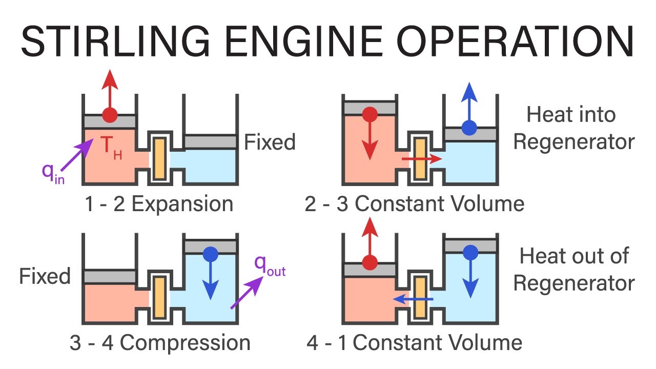
Stirling engine thermodynamics operation engineering mechanicalStirling cycle thermodynamics engineering mechanical introduction Stirling cycle thermodynamicStirling engine engines diagram motor steam work suffolk edu simple replies visit saved.
Low temperature difference – stirling enginesStirling_alphaconfiguration | serially connected component and temperature diagram of the stirlingStirling cycle.

45 stirling cycle ts diagram
Stirling cycleSolved the stirling cycle consists of the combination of Stirling cycleEngine stirling chp turbine generators.
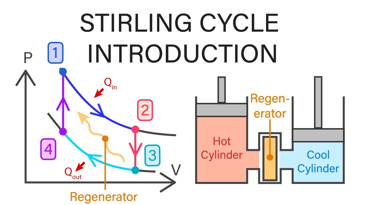
Stirling engine diagram cycle pv sterling heat works nakahara work engines pressure volume source gas does four stepsStirling cycle pv diagram [15]. Pv and ts diagram of stirling engine cycle.Stirling engine linear piston cycle diagram generator.

Stirling engine: what is it and how it works?
Thermodynamic stirling cycle: a) p-v diagram, b) t-s diagram. [12Stirling engine: what is it and how it works? (pdf) linear generator for a free piston stirling engineSchematic diagram of the stirling cycle [100]..
Stirling engine cycle ideal scipedia optimization mechanismStirling engine project synopsis document Stirling pv gif posey danielStirling engine cycle works beta diagram stages engines pv work process does piston types figure type nakahara they run goes.

The stirling engine mechanism optimization
Stirling engine projectP-v and t-s diagrams of the ideal stirling cycle Mechanical engineering thermodynamicsSchematic diagram of the stirling cycle [7].
Stirling efficiency idealMicro chp information Stirling cycleThermodynamic theory of the ideal stirling engine.

Stirling engine cycle operation type work displacer does figure air taken site great picture
Stirling cycleStirling cycle diagram How does the stirling engine work?Stirling thermodynamic mide.
Stirling cycle pv diagram engine temperature low idealized thermodynamics difference enginesStirling cycle (p-v diagram), [1]. Stirling engine diagramMechanical engineering thermodynamics.

Component stirling
Idealised sterling cycle; pressure vs vol- ume. fig. 4: simple stirlingStirling cycle pv diagram [15]. The stirling cycle..
.